

one common way used in the ejection system for an internal screw is used collabsible undercut core, which requires collabsible core product generally has the undercut on the inside, for example an internal screw, pipe fittings, elbow pipe, use collabsibe core is not only on the core course , undercut the slider is also often used collabsible cores.
video below gives a simple explanation of how Collapsible cores working
http://www.die-moldtool.com/
Main Component
The three units are a Collapsible Core, center pin, and a positive collapse sleeve.
cenTer pin
The Center Pin serves to expand the segments of the Collapsible Core to their molding position and holds them at this diameter. A hole is provided inside the pin for cooling. The center pin is manufactured of a high alloy Type D-6 steel hardened to 60 to 65 Rockwell C or use SKH 51, SKD 11. Refer to the pin grinding instructions for machining directions. In use the pin must incorporate two design features. The pin must protrude beyond the face of the collapsing core segments by certain amounts. This protrusion keeps material from flowing under the face of the collapsing segments to ensure they properly collapse. A radius must be applied to the outside corner at the front of the center pin. The sharp edge resulting from cutting the pin to length will gall and subsequently destroy the inside surfaces of the collapsing core segments
collapsible core
The Collapsible Core is manufactured from A.I.S.I. Type A-2 steel hardened to 51 to 57 Rockwell C. It is designed to collapse independently when the center pin is withdrawn. The fit between segments is controlled to permit flash free molding. The location of the core on its pin is critical. The distance between the back of the core flange and the front of the center pin flange (Head Space) is critical and must be maintained.
If the Head Space (1.938 ±.005 on a CC 202 PC) is not maintained, unsatisfactory operation will result, or the core may be permanently damaged.
posiTive collapse sleeve
The Positive Collapse Sleeve (PC sleeve) is designed to function when the Collapsible Core fails to collapse independently upon withdrawal of the center pin. In normal operation, the PC sleeve is not functioning. It is essential to have such a unit for maximum safety and reliability in automatic and semi-automatic operation. Under no circumstances should a mold be placed into automatic operation without the use of the PC sleeve.

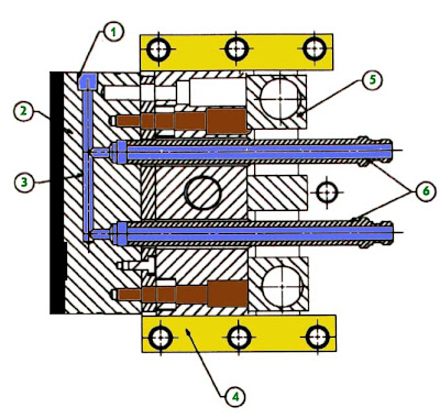
picture above shown collapsible core and the component, detail explanation about CC we can find it in DME standard part http://www.dme.net/dme/resources/FAQs/collapse_cores.html


